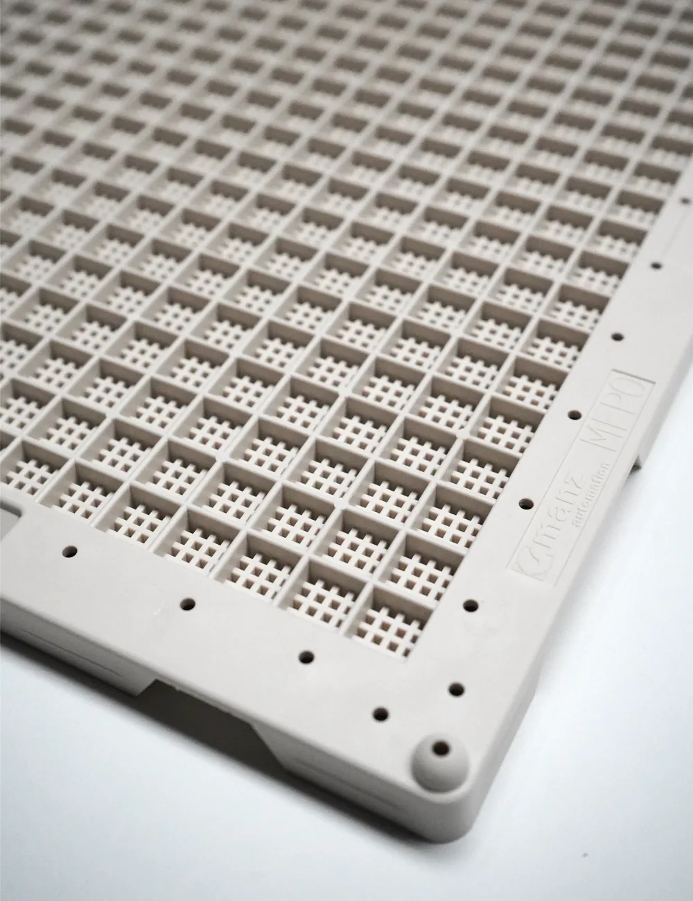
Outer size: the interface to the surroundings
The outer contour becomes relevant when a carrier is used in a guide, a magazine or a shelf. Besides length and width, height, feet, projections or locating points can play a role. Use a current drawing for this. A photo shows the shape but does not provide reliable tolerances.
Grid pitch: the repeating arrangement
The grid describes a distance within a repeated pattern, for example between corresponding positions of adjacent pockets. It is not automatically identical to the free opening of a pocket. Wall thicknesses and other geometry can change the usable space. The drawing must show which reference points are meant.
Usable pocket size: the real holding space
For the part, what counts is the available contour in the intended position. Check webs, radii and the support on the floor. For a part with a projection, the narrowest free point can matter more than the largest opening. A tilted or inclined position also changes the space needed.
Simplified calculation example
Suppose a rectangular part is nominally 20 mm wide and a straight pocket offers 22 mm of free width. Mathematically that leaves 2 mm in total, i.e. 1 mm per side if centred. That is not yet proof for approval: part tolerance, pocket tolerance, alignment and the necessary gripper space are not taken into account. The example does not describe an MFP dimension.
Height is part of the picture
Don’t just measure how deep a pocket is. What matters is the overall height of the loaded workpiece relative to adjacent parts, covers or a carrier above it. A protruding part can be unremarkable at rest and only collide during the next handling step.
A practical check procedure
Mark the intended part position in a sketch. Enter the largest and smallest relevant dimensions. Add the space needed for removal and then assess the sample. Record observations such as tipping, jamming or unwanted contact points. This combination produces a more reliable statement than a single comparison of figures.